Posts

Showing posts with the label AutoCAD 2D Draw Commands

Hide / Show Startup Window in AutoCAD Software.

Image
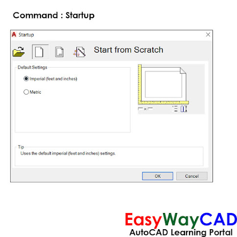
Hello, Friends Today We will learn about Startup Command in AutoCAD. Command : Startup - Hide / Show Startup Window in AutoCAD Software. Value                    Description     0                         Starts a drawing without defined settings.     1                         Display Startup Dialog Box.       2                         Startup with Custom Dialog displayed.     3                         Startup Dialog Box with preloaded Ribbon. Start from  scratch Default Settings: Select setting whether Imperial or Metric. Open a drawing Show the list of recently open drawings. We can open drawing from Browse Button. Select a template Select template settings from the list. Select a wizard We can select Drawing settings using Advance Setup or Quick Setup. I hope You Like this Post. Subscribe to this blog so you can get regular updates about this blog! If you have any doubt you can comment, we will reply to you as soon as possible. you can share this post with your friends, relative &

How to add symbols in dtext and mtext using special characters?

Image
Hello, Friends Today We learn how to add symbols in Text using special characters. Using Special Characters We can add Diameter, Degree, Plus/Minus, Underline and Overline Symbols in Text. For Diameter use %%C , For Degree use %%D , For Plus/Minus use %%P, For Underline use %%U, For Overline use %%O For Underline , add %%U before and after Text. For Overline , add %%O before and after Text.   I hope You Like this Post. Subscribe to this blog so you can get regular updates about this blog! If you have any doubt you can comment, we will reply to you as soon as possible. you can share this post with your friends, relative & Colleagues. In the next post, we will learn New AutoCAD Command / Topic. - Bhargav Joshi

How to hide or mask objects using Wipeout Command in AutoCAD Drawing?

Image
COMMAND : WIPEOUT SHORT-CUT : WI MENU : DRAW > WIPEOUT - Creates a wipeout objects and also control whether wipeout frames are displayed or plotted in the drawing. First Point Determines the polygonal boundary of the wipeout object from a series of points. Frames Determines whether the edges of all wipeout objects are displayed or hidden. Frames modes: ON - frames are displayed and plotted OFF - frames are not displayed or plotted Display but not plot - frames are displayed but are not plotted Polyline Determines the polygonal boundary of the wipeout objects from a selected polyline. Erase Polyline Enter y to erase the polyline that was used to create the wipeout object. Enter n to retain the polyline. Wipeout Command YouTube Command Link: I hope You Like this Post. Subscribe to this blog so you can get regular updates about this blog! If you have any doubt you can comment, we will reply to you as soon as possible. you can share this post with your friends, relative & Colleagues

How to Apply Gradient in Objects in AutoCAD Drawing?

Image
Hello, Friends Today We Learn How to Apply Gradient in Objects in AutoCAD Drawing.  Command : Gradient Short-cut : GD Menu : Draw > Gradient - We can apply Gradient Color effect in Selected Object or Internal Boundary of Object in AutoCAD Drawing. Gradient Fill applies with Single or Two Colors. Color         Single Color : Select One Color. Apply Nine ready effects with Single Color with                               Shade(Black ) or Tint (White) Color.         Two Colors : Select Two Colors. Apply Nine Ready effects with Two Selected Colors. Orientation         Centered : Specifies a Symmetrical gradient configuration. If this option is selected then              effect apply in centered. If this option is not selected then effect apply in left top side.          Angle : Change the gradient fill effect by rotation angle. By default, Angle value is Zero.   Boundaries      Add : Pick Points     Mouseclick in internal Part of Object to Apply Gradient in Particular Region of Object.

How to Apply Hatch in objects in AutoCAD Drawing?

Image
  Hello, Friends Today We learn How to Apply Hatch Patterns in AutoCAD Drawing. Command : Hatch Short-cut : H Menu : Draw > Hatch Apply Hatch Patterns or Solid Fill in Internal Boundary of Object or in Selected Objects. Patterns Apply Different Types of Patterns from ANSI ( American National Standard Institute), ISO (International Standardization Organization) ,Other Predefined or Custom (.pat) options. Color  Select Hatch Pattern Color and Background Fill color for Hatch Pattern. Swatch Show the Thumbnail of Selected Hatch Pattern. Boundaries     Add : Pick Points     Mouseclick in internal Part of Object to Apply Hatch in Particular Region of Object.     Add : Select Objects     Select Objects to apply Hatch in Selected Objects in AutoCAD Drawing. Angle : Rotate Hatch Pattern with Specified Rotation Angle. Select Rotation Angle from List or We can type own Rotation Angle. Default Angle = 0. Scale : We can Select Hatch Pattern Scale from List or We can Type own Scale Factor. Defaul

How to Draw a Multiline in AutoCAD Software?

Image
  Hello, Friends Today We learn about Multiline Command in AutoCAD Software. COMMAND: MULTILINE SHORT-CUT: ML MENU : DRAW > MULTILINE - Multiline is a combination of Two or more Parallel Lines.We can explode Multiline and convert it into seprate lines. We can close Multiline using the Close Option. If We draw Multiline using Standard Style then only Two Parallel Lines are created. Scale(s) : Scale is considered as per Current Units in the Drawing. By Default, the Scale Value is 1.0 We can increase or Decease Value as per Drawing Requirements. If We take Scale Value Zero then only Single line is Created. Justification(j) : Specify the Justification for Multiline Top,Zero,Bottom. Justification determnines by from which side multiline is drawn. STyle(st) : Specify the Multiline Style for Multiline.By Multiline Style, We Can Create New Line & Modify Line.Rename & Delete Line from Multilines. Offset Distance of line from Middle line. Color & Linetype properties of each line.

How to Draw a Spline Curve in AutoCAD Software?

Image
Hello, Friends Today We will learn Spline Command in AutoCAD Software.  Command : Spline Short-cut : Spl Menu : Draw > Spline - Draw a Nonuniform Rational B-Spline(NURBS) curve passing through or near a set of fit points / Vertices. There are two options to draw a Spline : a) Fit b) Control Vertices(CV) We can draw a spline using many Fit points or many Vertices. Close(c) : Close Spline curve by joining Last point to Starting point. Method : Control whether the Spline Curve is created by Fit points or with Control Vertices.       Fit(f) :   Creates a degree 3 (cubic) B-spline by specifying fit points that the spline must pass through.              Knots(k) : Specify options when we choose Fit Method.             a)  Chord. ( Chord-Length method) Spaces the knots connecting each component curve to be proportional to the distances between each associated pair of fit points. An example is the green curve in the illustration.             b)  Square root. (Centripetal method) Spac

Draw Xline or Construction line in AutoCAD Software

Image
  Hello, Friends Today We will learn about Construction line / Xline in AutoCAD Software. Command : Xline Short-cut : Xl Menu : Draw > Construction Line - Construction line is a line with both sides infinite length. We can used construction line as reference line in drawing.Constuction line also known as Xline. We can trim Construction line. We can't give any dimension like Linear, Aligned dimension. Hor : Creates a Horizontal Xline passes through a point. Ver : Creates a Vertical Xline passes through a point. Ang : Creates a Xline at specific Angle or Reference which passes through a point. Bisect : Creates a Xline passes through angle vertex point and Bisect the Angle between Start point and End point. Offset : Creates a Xline Parallel to line, Xline or object. We can specify offset distance or we can create Xline Parallel to object by passing through a point.  Xline Command YouTube Video Link:     I hope You Like this Post. Subscribe this blog so you can get regular updat

How to use Ray in AutoCAD Software?

Image
  Hello, Friends Today We will learn Ray Command in AutoCAD Software. Command : Ray Menu : Draw > Ray - We can Draw Ray using Starting Point & Through Point. After Specifying Start point, We can draw multiple rays by clicking different through points. So Basically Ray is one sided infinite lines which have starting point but doesn't have ending point.   We can use Ray as Reference lines in AutoCAD Drawing. We can also use Ray for Projection of objects in Drawing. Ray Command YouTube Video Link: I hope You Like this Post. Subscribe this blog so you can get regular updates about this blog! If you have any doubt you can comment, we will reply to you as soon as possible. you can share this post with your friends, relative & Colleagues. In the next post, we will learn New AutoCAD Command / Topic. - Bhargav Joshi

How to Use Mirrtext Command in AutoCAD Software?

Image
  Hello, Friends Today We learn about Mirrtext Command in AutoCAD Software. COMMAND : MIRRTEXT By This Command, We can control Whether the text will mirrored or not. Value                                   Description      0                    Retain Text, Text orientation will not change.     1                    Mirror the Text, Text orientation will change. MIRRTEXT VALUE =0 MIRRTEXT VALUE=1 After Change Value in Mirrtext Command, We have to Mirror text again. By Default, Mirrtext value is 0. See Mirrtext YouTube Video:   I hope You Like this Post. Subscribe this blog so you can get regular updates about this blog! If you have any doubt you can comment, we will reply to you as soon as possible. You can share this post with your friends, relative & Colleagues. In the next post, we will learn New AutoCAD Command / Topic. - Bhargav Joshi

How to write Mtext in AutoCAD Software?

Image
  Hello, Friends Today We will learn Multiline Text(MText) In AutoCAD Software. COMMAND : Mtext Short-cut : MT Menu : Draw > Text > Multiline Text By Mtext Command, We can write Paragraph Text or Multilines in AutoCAD.There are many advantages in Mtext like Formatting Tools, Paragraph, Symbols, Columns. Type "Mtext" Command, then Specify First and opposite corner on screen by Mouseclick. Write Text inside Mtext Window. We can change Text Style, Text Font, Text Height & Annotation option from Formatting Tools.We can Apply Bold & Italic Effect on True type Fonts.We can also Apply Underline & Overline to Selected Text. Oblique Angle : Write Slant Text using Oblique Angle. Angle should be between -85 to +85. Tracking : Adjust the spacing between Text Characters. Min.0.75 & Max.4.0 Value. Width Factor : Narrow or Widen Selected Text. Min.0.1 & Max.10.0 Stack: We can add horizonal line, diagonal line, Tolerance value using Slash (/), Pound(#) & Carat