Posts

Showing posts from August, 2020

Properties Command in AutoCAD Software

Image
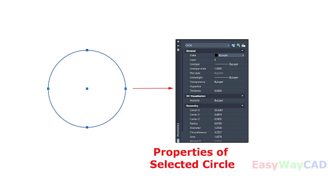
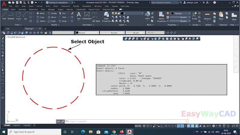
  Hello, Friends Today We will learn about Properties Command in AutoCAD Software. Command: Properties Short-cut : PR /MO / CH/ Ctrl+1 - We can See & Change the Properties of Selected Object. Common AutoCAD 2D Properties are Color, Linetype, Lineweight, Linetype Scale, Layer, Transparency, Thickness. We can also see & change the Special properties of the selected objects.E.g.For line, Start(x,y,z) ,End(x,y,z), Delta(x,y,z), Length, Angle For Circle, Center(x,y,z), Radius, Diameter, Area, Circumference. I hope You Like this Post. Subscribe this blog so you can get regular updates about this blog! If you have any doubt you can comment, we will reply to you as soon as possible.you can share this post with your friends, relative & Colleagues. In the next post, we will continue to about AutoCAD Commands. - Bhargav Joshi

How to use Explode Command in AutoCAD Software?

Image
  Hello, Friends Today We Will learn about Explode Command in AutoCAD Software. COMMAND: EXPLODE SHORT-CUT: X MENU : MODIFY > EXPLODE TOOL ICON :  - Creates Components objects from a Compound Object. Explode Command breaks a Compound Object into Components objects. We Can explode 2D Polyline,3D Polyline, Multiline, Multiline Text, Associative Array objects, Hatch Pattern, Block, Leader, Dimension. We Can't explode single entity objects like Line, Circle, Arc, Ellipse, Elliptical Arc, Spline, Xline, Point, Text. We can explode text by TXTEXP Command. Explode Command YouTube Video : https://youtu.be/na2xRsN0lg8 I hope You Like this Post. Subscribe this blog so you can get regular updates about this blog! If you have any doubt you can comment, we will reply to you as soon as possible.you can share this post with your friends, relative & Colleagues. In the next post, we will continue to about AutoCAD Commands. - Bhargav Joshi

How to create polyline or region object from Boundary Command in AutoCAD Software?

Image
  Hello, Friends Today We will learn about Boundary Command in AutoCAD Software. Command: Boundary Short-cut: Bo Menu: Draw > Boundary - By Boundary Command, We can create Region or Polyline Object from Closed Bounded ( Enclosed) Objects. Pick Points: By this Option, A boundary is determined from existing objects that form an enclosed area around a specific point. Island Detection: By this option, We can controls whether internal boundaries ( Island) are detected or not. If We Check this option, then All internal boundaries create regions or polylines objects. Object Type: Controls New Boundary create a Region object or Polyline object. Boundary Set: Selected objects are form a Boundary set while analysing boundary.         Current Viewport: Create a New Boundary set in Current Viewport.         New : We can selecte objects which define new Boundary Set.Boundary includes only thosed objects which create a region or polyline object when construct a new boundary set. Boundary Comm

How to convert selected objects into Region object in AutoCAD Software?

Image
Hello, Friends Today We will learn about Region Command in AutoCAD Software. COMMAND: REGION SHORT-CUT: REG MENU: DRAW > REGION Convert Selected Closed bounded (Enclosed Area) objects into Region Object. We can select Lines, Arcs, Polylines, Ellipses, Elliptical Arcs & Splines to Create Region Object. Crossing & Self intersect objects are not valid to create a Region Object. We can use Union, Subtract & Intersect Commands on Region objects. We can't Stretch Region Objects. We can also use Boundary Command to create a Region Object. Region Command YouTube video :  https://youtu.be/M9rZSzMvkQ0 I hope You Like this Post. Subscribe this blog so you can get regular updates about this blog! If you have any doubt you can comment, we will reply to you as soon as possible.you can share this post with your friends, relative & Colleagues. In the next post, we will continue to about AutoCAD Commands. - Bhargav Joshi

How to see X,Y,Z Co-ordinate of Specified Point by ID Command in AutoCAD?

Image
Hello, Friends Today We Will learn about ID Command. COMMAND: ID MENU: TOOLS > INQUIRY > ID Point - Show the X, Y & Z Co-ordinate of Specified Point. It also stores the co-ordinate of the specified point as the last point. We can reference the last point by entering @ at the next point that requests the point.    Command results shown in Command line Text Window. Result: Command: ID Specify point:  X = 4.0000     Y = 4.0000     Z = 0.0000 The above Result shows the X, Y & Z Co-ordinate of that specified point. ID Command YouTube Video :  https://youtu.be/tDosU2OgiAg I hope You Like this Post. Subscribe this blog so you can get regular updates about this blog! If you have any doubt you can comment, we will reply to you as soon as possible.you can share this post with your friends, relative & Colleagues. In the next post, we will continue to about AutoCAD Commands. - Bhargav Joshi

How to see properties of selected object by List Command?

Image
Hello, Friends Today We will learn about List command. COMMAND: LIST SHORT-CUT: LI MENU: TOOLS > ENQUIRY>LIST - Show the properties of the selected object. When you select an object it shows properties of that object in the Command line text window. Show the properties like Object type, Layer, Model/Paper Space in 2D Object. Show the Color, Linetype & Lineweight Properties ( If it is not Bylayer) in 2D Object. Show the thickness value (If it is not Zero) in 2D Object. Properties as per object e.g. If you select circle then List command shows Centerpoint, Radius, Circumference & Area. If you select Line then List command shows Start point (x,y,z), Endpoint (x,y,z), Length, Delta X, Delta Y, Delta Z, Angle in XY Plane. See List command Example in below fig. List Command YouTube Link :  https://youtu.be/tDosU2OgiAg I hope You Like this Post. Subscribe this blog so you can get regular updates about this blog! If you have any doubt you can comment, we will reply to you as soon

How to draw an isocircle in AutoCAD Software without using Isometric snap?

Image
  Hello, Friends Today We will see how to draw an Isocircle without using Isometric Snap. First Draw Cube by lines in 2D Using Polar Tracking: ON. Take Increment Angle value 30 so we can draw lines on 30,90 & 150 angles. Use F10 key or Ctrl+U to ON Polar Tracking or Click on the Status bar. Now Draw Circle and use trim to draw an isocircle. See below Fig. To see in detail. See youtube Video. Isocircle Youtube Video Link:  https://youtu.be/YSavWn6tIFE I hope You Like this Post. Subscribe this blog so you can get regular updates about this blog! If you have any doubt you can comment, we will reply to you as soon as possible.you can share this post with your friends, relative & Colleagues. In the next post, we will continue to about AutoCAD Commands. - Bhargav Joshi Follow, Subscribe, Share &  Like Page: Email us: easywaycad@gmail.com  for any query.