Posts

Hide / Show Startup Window in AutoCAD Software.
Image
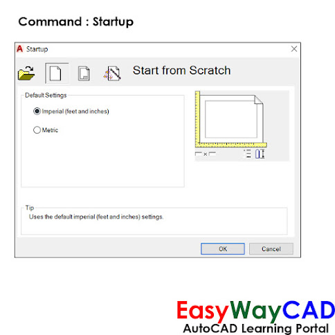
Hello, Friends Today We will learn about Startup Command in AutoCAD. Command : Startup - Hide / Show Startup Window in AutoCAD Software. Value                    Description     0                         Starts a drawing without defined settings.     1                         Display Startup Dialog Box.       2                         Startup with Custom Dialog displayed.     3                         Startup Dialog Box with preloaded Ribbon. Start from  scratch Default Settings: Select setting whether Imperial or Metric. Open a drawing Show the list of recently open drawings. We can open drawing from Browse Button. Select a template Select template settings from the list. Select a wizard We can select Drawing settings using Advance Setup or Quick Setup. I hope You Like this Post. Subscribe to this blog so you can get regular updates about this blog! If you have any doubt you can comment, we will reply to you as soon as possible. you can share this post with your friends, relative &

How to add symbols in dtext and mtext using special characters?

Image
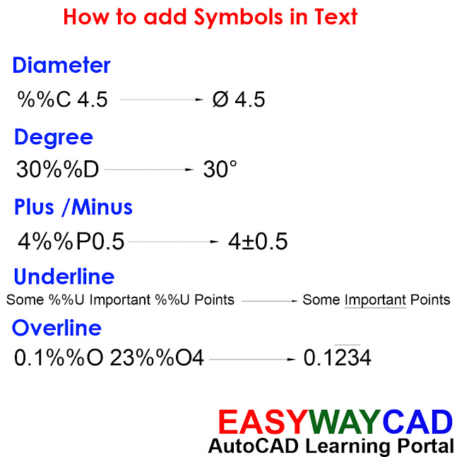
Hello, Friends Today We learn how to add symbols in Text using special characters. Using Special Characters We can add Diameter, Degree, Plus/Minus, Underline and Overline Symbols in Text. For Diameter use %%C , For Degree use %%D , For Plus/Minus use %%P, For Underline use %%U, For Overline use %%O For Underline , add %%U before and after Text. For Overline , add %%O before and after Text.   I hope You Like this Post. Subscribe to this blog so you can get regular updates about this blog! If you have any doubt you can comment, we will reply to you as soon as possible. you can share this post with your friends, relative & Colleagues. In the next post, we will learn New AutoCAD Command / Topic. - Bhargav Joshi

Snapstyl , Snapisopair & Fillmode System Variables in AutoCAD.

Image
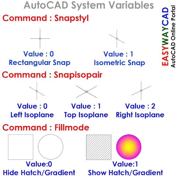
Hello, Friends Today We learn Important & Useful AutoCAD System Variables.  Command : Snapstyl - Change Snap Style : Rectangular or Isometric Snap. Value                    Description     0                    Rectangular Snap     1                    Isometric Snap Command : Snapisopair - Change Isoplane Left , Top or Right Isoplane. Value                    Description     0                    Left Isoplane     1                         Top Isoplane     2                    Right Isoplane Command : Fillmode - Hide/Show Hatch, Gradient and Solid fill in Object. Value               Description     0                    Hide Hatch, Gradient and Solid fill in Object.     1                    Show Hatch, Gradient and Solid fill in Object. Use Regen Command after changing Value in Fillmode Command. I hope You Like this Post. Subscribe to this blog so you can get regular updates about this blog! If you have any doubt you can comment, we will reply to you as soon as possible. you can sha

Mirrhatch & Filedia System Variables in AutoCAD Software

Image
Hello, Friends Today We learn Mirrhatch & Filedia system variables command in AutoCAD. Command : Mirrhatch - Retain or Mirror Hatch Pattern in object. Value             Description     0                           Retain Hatch Pattern in object     1                           Mirror Hatch Pattern in object. Command : Filedia - Control to use Dialogue Box While operating Command in AutoCAD. Value              Description     0                     Dialogue Box is not open while using New, Open , Save and Save as                                                 Command. We have to use it from Command line Window.     1                     Show Dialogue Box while operating Command in AutoCAD.   I hope You Like this Post. Subscribe to this blog so you can get regular updates about this blog! If you have any doubt you can comment, we will reply to you as soon as possible. you can share this post with your friends, relative & Colleagues. In the next post, we will learn New AutoCAD Comma

Attach or Detach Leader to Text or Block Object using Qlattach and Qldetachset Command.

Image
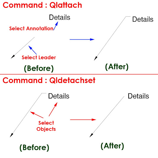
Hello, Friends Today We learn How to use Qlattach and Qldetachset Comamnd. COMMAND : Qlattach SHORT-CUT : Qla MENU : Express > Dimension > Leader Tools > Attach Leader to Annotation - Attaches a leader line to Mtext or Block Object. First Select Leader then Select Mtext or Block Object as Annotation. COMMAND : Qldetachset SHORT-CUT : Qld MENU : Express > Dimension > Leader Tools > Detach Leaders from Annotation - Detaches a leader line to Mtext or Block Object. Select Both Leader Line and Mtext or Block Annotation.   I hope You Like this Post. Subscribe to this blog so you can get regular updates about this blog! If you have any doubt you can comment, we will reply to you as soon as possible. you can share this post with your friends, relative & Colleagues. In the next post, we will learn New AutoCAD Command / Topic. - Bhargav Joshi

How to export & import Dimension Style using Dimex and Dimin Commands?

Image
Hello, Friends Today We learn How to Export Dimension Style using Dimex and Import Dimension Style using Dimin Command.  COMMAND : DIMEX MENU : EXPRESS > DIMENSION > DIMSTYLE EXPORT... - Export Selected Dimension style in .dim (ASCII) file format. Export File Name Specify .dim File Name and Save file path using Browse option. Text Style Options Text Style Name Only : Save Text Style Name only in .dim ASCII File. Full Text Style Information : Save Full Text Style Information in .dim ASCII File. COMMAND : DIMIM MENU : EXPRESS > DIMENSION > DIMSTYLE IMPORT... - Import Dimension style from selected .dim (ASCII) file. Import Filename Specifies the ASCII text file to import. By default, the file has a DIM extension, and the file must be in the format generated by the DIMEX Express Command. Import Options Keep Existing Style :  The Keep the Existing Style option ignores the similarly named style being imported. Overwrite Existing Style :  Overwrite Existing Style uses the simila

How to hide or mask objects using Wipeout Command in AutoCAD Drawing?

Image
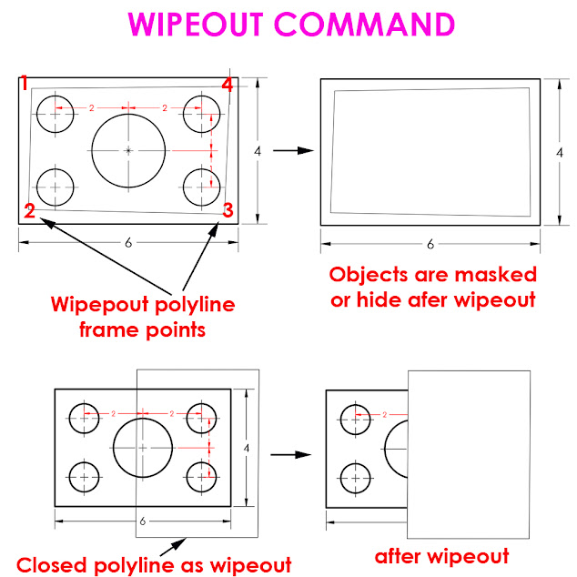
COMMAND : WIPEOUT SHORT-CUT : WI MENU : DRAW > WIPEOUT - Creates a wipeout objects and also control whether wipeout frames are displayed or plotted in the drawing. First Point Determines the polygonal boundary of the wipeout object from a series of points. Frames Determines whether the edges of all wipeout objects are displayed or hidden. Frames modes: ON - frames are displayed and plotted OFF - frames are not displayed or plotted Display but not plot - frames are displayed but are not plotted Polyline Determines the polygonal boundary of the wipeout objects from a selected polyline. Erase Polyline Enter y to erase the polyline that was used to create the wipeout object. Enter n to retain the polyline. Wipeout Command YouTube Command Link: I hope You Like this Post. Subscribe to this blog so you can get regular updates about this blog! If you have any doubt you can comment, we will reply to you as soon as possible. you can share this post with your friends, relative & Colleagues