Posts

Showing posts from November, 2020

How to use Textmask Command in AutoCAD Drawing?

Image
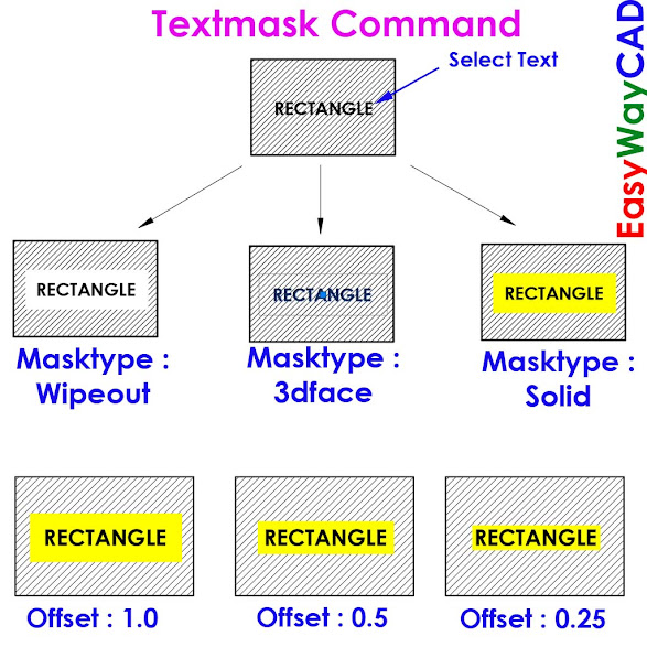
Hello, Friends Today We learn Textmask Command in AutoCAD. Command : Textmask Menu : Express > Text > Text Mask - Create a mask ( Blanked Space ) behind Selected Text or Mtext Objects. Options Wipeout: Creates a wipeout object with a rectangular frame displayed in the graphics background color. 3dface: Creates a 3D face object. Solid: Creates a 2D solid object in a specified color. Wipeout Masking is done with Blanked Rectangle Area. Masking does not plot properly if the Hide Lines option is used while plotting. One advantage of using a Wipeout mask is that what you see on screen is what you get on your plot. 3Dface The 3Dface created by TEXTMASK has all of its edges set to invisible. This option is useful if you do not have a raster-capable plotter. The Hide Lines option must be used while plotting for the mask effect to work. With this option, masked text does not look masked on screen. Solid With Solid option, masked text appears masked in the drawing area. Also, masks c

How to use Tcount Command in AutoCAD Drawing?

Image
Hello Friends, Today We learn Tcount Command in AutoCAD. Command : Tcount Menu : Express > Text > Automatic Text Numbering - Add Sequential Numbering to Selected Text or Mtext as Prefix, Suffix or Replacement Text.   Select Objects : Select text or Mtext Objects X :    Determines numeric order by increasing x-coordinate values of the selected text. Y :  Determines numeric order by decreasing the y-coordinate value of the selected text. Select-order : Determines numeric order according to the order in which the text was selected. Enter count [Start, increment] <current>: Enter the starting number and increment, separated by a comma, or press Enter Start           Specifies the first number in the sequence. Increment Specifies the difference between the numbers in the sequence. Note : We can also add negative value as increment value. Add minus (-) sign before value. Overwrite              Replaces selected text strings with numbers Prefix              Adds the number

How to use change Command in AutoCAD Drawing?

Image
Hello, Friends Today We learn Change Command in AutoCAD Drawing. Command : Change - Change the Properties of Selected Objects in AutoCAD Drawing. Change Point or Value Change the properties of selected object. It Depends upon Type of object that you select. Line : Change the endpoint of Selected line. Location of endpoint is depend upon Ortho On/Off. Circle : Change the radius of Selected Circle. Text : Change the location of Selected Text. Properties(P) Change the Properties of Selected Object Like Color, Linetype, LineWeight, Linetype Scale, Layer, Elevation, Thickness, Annotative, Material and Transparency.     Color(c) : Change the Color Property of Selected Object. Change Color using True Color          (RGB Value) or by ColorBook.     LType(lt) : Change the linetype of Selected Object. e.g. Dashed, Center     ltScale(s) : Change the linetype scale of Selected Object.     LWeight(lw) : Change the lineweight of Selected Object.     LAyer(la) : Change the layer of Selected Object.

How to use purge Command in AutoCAD Drawing?

Image
Hello, Friends Today We learn Purge Command in AutoCAD. Purge Command is used to remove unused & unreferenced items like Layers, Blocks, Dimension Style, Text Style, Linetypes etc... in AutoCAD Drawing. We can used Purge Command to clean up AutoCAD Drawing to remove unused items. Removing unused items can reduce file size and also reduces clutter. Command : Purge Short-cut : Pu Menu : File > Drawing Utilities > Purge There are two options in Purge Dialog Box. - Purgeable Items - Find Non-Purgeable Items Purgeable Items  List the items that we can purge from list in current AutoCAD Drawing. Preview Click on item in list to see preview of Item. Confirm Each item to be purged Display Confirm Dialog Box when we purge item. Purge Nested Items Removes all unused named objects from the drawing even if they are contained within or referenced by other unused named objects. Purge Unnamed Objects           Zero-length geometry           Deletes geometry of zero length, including lines,

How to insert Raster Image in the AutoCAD Drawing?

Image
  Hello, Friends Today We learn How to Insert Raster Image in AutoCAD Drawing, How to Adjust Raster Image and Image Border in AutoCAD Drawing. Command : Imageattach Short-cut : iat Menu : Insert > Raster Image Reference Attach Raster Image Reference File in AutoCAD Drawing. Image is placed as reference file in AutoCAD Drawing So we can change and remove image file anytime. Scale We can scale image with scale factor Value. We can directly scale on screen or from Attach image window. Rotation We can Rotate image with Rotation Angle. We can directly Rotate on Screen or from Attach Image Window. Insertion Point We can specify Insertion Point (x, y, z) on screen or from attach image window. Supported Raster Image File Formats Format Extension Adobe Photoshop Format . psd Arc/Info ASCII Grid Format . asc , . txt Arc/Info Binary Grid Format . adf Autodesk Animator

How to Rename items like Text styles, Dimension Styles, Blocks in the AutoCAD Drawing?

Image
  Hello, Friends Today We learn How to Rename Items like Dimension Styles, Text Style, Layers, Blocks etc in the AutoCAD Drawing. First Select the Named Objects like Dimension Style, Text Style, Blocks, Layers etc... then Select items from list. Select item is as Old Name, Now Type New name in Rename to Box. I hope You Like this Post. Subscribe to this blog so you can get regular updates about this blog! If you have any doubt you can comment, we will reply to you as soon as possible. you can share this post with your friends, relative & Colleagues. In the next post, we will learn New AutoCAD Command / Topic. - Bhargav Joshi