Posts

Showing posts from September, 2020

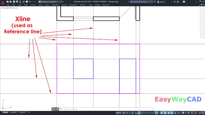
How to Draw a Multiline in AutoCAD Software?

Image
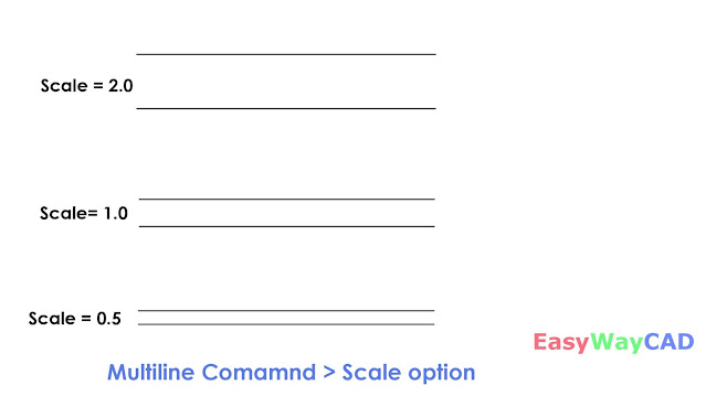
  Hello, Friends Today We learn about Multiline Command in AutoCAD Software. COMMAND: MULTILINE SHORT-CUT: ML MENU : DRAW > MULTILINE - Multiline is a combination of Two or more Parallel Lines.We can explode Multiline and convert it into seprate lines. We can close Multiline using the Close Option. If We draw Multiline using Standard Style then only Two Parallel Lines are created. Scale(s) : Scale is considered as per Current Units in the Drawing. By Default, the Scale Value is 1.0 We can increase or Decease Value as per Drawing Requirements. If We take Scale Value Zero then only Single line is Created. Justification(j) : Specify the Justification for Multiline Top,Zero,Bottom. Justification determnines by from which side multiline is drawn. STyle(st) : Specify the Multiline Style for Multiline.By Multiline Style, We Can Create New Line & Modify Line.Rename & Delete Line from Multilines. Offset Distance of line from Middle line. Color & Linetype properties of each line.

How to Draw a Spline Curve in AutoCAD Software?

Image
Hello, Friends Today We will learn Spline Command in AutoCAD Software.  Command : Spline Short-cut : Spl Menu : Draw > Spline - Draw a Nonuniform Rational B-Spline(NURBS) curve passing through or near a set of fit points / Vertices. There are two options to draw a Spline : a) Fit b) Control Vertices(CV) We can draw a spline using many Fit points or many Vertices. Close(c) : Close Spline curve by joining Last point to Starting point. Method : Control whether the Spline Curve is created by Fit points or with Control Vertices.       Fit(f) :   Creates a degree 3 (cubic) B-spline by specifying fit points that the spline must pass through.              Knots(k) : Specify options when we choose Fit Method.             a)  Chord. ( Chord-Length method) Spaces the knots connecting each component curve to be proportional to the distances between each associated pair of fit points. An example is the green curve in the illustration.             b)  Square root. (Centripetal method) Spac

Draw Xline or Construction line in AutoCAD Software

Image
  Hello, Friends Today We will learn about Construction line / Xline in AutoCAD Software. Command : Xline Short-cut : Xl Menu : Draw > Construction Line - Construction line is a line with both sides infinite length. We can used construction line as reference line in drawing.Constuction line also known as Xline. We can trim Construction line. We can't give any dimension like Linear, Aligned dimension. Hor : Creates a Horizontal Xline passes through a point. Ver : Creates a Vertical Xline passes through a point. Ang : Creates a Xline at specific Angle or Reference which passes through a point. Bisect : Creates a Xline passes through angle vertex point and Bisect the Angle between Start point and End point. Offset : Creates a Xline Parallel to line, Xline or object. We can specify offset distance or we can create Xline Parallel to object by passing through a point.  Xline Command YouTube Video Link:     I hope You Like this Post. Subscribe this blog so you can get regular updat

How to use Ray in AutoCAD Software?

Image
  Hello, Friends Today We will learn Ray Command in AutoCAD Software. Command : Ray Menu : Draw > Ray - We can Draw Ray using Starting Point & Through Point. After Specifying Start point, We can draw multiple rays by clicking different through points. So Basically Ray is one sided infinite lines which have starting point but doesn't have ending point.   We can use Ray as Reference lines in AutoCAD Drawing. We can also use Ray for Projection of objects in Drawing. Ray Command YouTube Video Link: I hope You Like this Post. Subscribe this blog so you can get regular updates about this blog! If you have any doubt you can comment, we will reply to you as soon as possible. you can share this post with your friends, relative & Colleagues. In the next post, we will learn New AutoCAD Command / Topic. - Bhargav Joshi

How to Use Mirrtext Command in AutoCAD Software?

Image
  Hello, Friends Today We learn about Mirrtext Command in AutoCAD Software. COMMAND : MIRRTEXT By This Command, We can control Whether the text will mirrored or not. Value                                   Description      0                    Retain Text, Text orientation will not change.     1                    Mirror the Text, Text orientation will change. MIRRTEXT VALUE =0 MIRRTEXT VALUE=1 After Change Value in Mirrtext Command, We have to Mirror text again. By Default, Mirrtext value is 0. See Mirrtext YouTube Video:   I hope You Like this Post. Subscribe this blog so you can get regular updates about this blog! If you have any doubt you can comment, we will reply to you as soon as possible. You can share this post with your friends, relative & Colleagues. In the next post, we will learn New AutoCAD Command / Topic. - Bhargav Joshi

How to write Mtext in AutoCAD Software?

Image
  Hello, Friends Today We will learn Multiline Text(MText) In AutoCAD Software. COMMAND : Mtext Short-cut : MT Menu : Draw > Text > Multiline Text By Mtext Command, We can write Paragraph Text or Multilines in AutoCAD.There are many advantages in Mtext like Formatting Tools, Paragraph, Symbols, Columns. Type "Mtext" Command, then Specify First and opposite corner on screen by Mouseclick. Write Text inside Mtext Window. We can change Text Style, Text Font, Text Height & Annotation option from Formatting Tools.We can Apply Bold & Italic Effect on True type Fonts.We can also Apply Underline & Overline to Selected Text. Oblique Angle : Write Slant Text using Oblique Angle. Angle should be between -85 to +85. Tracking : Adjust the spacing between Text Characters. Min.0.75 & Max.4.0 Value. Width Factor : Narrow or Widen Selected Text. Min.0.1 & Max.10.0 Stack: We can add horizonal line, diagonal line, Tolerance value using Slash (/), Pound(#) & Carat

How to create & Modify Text style in AutoCAD Software?

Image
  Hello, Friends Today We learn how to create and modify Text style in AutoCAD Software. Command : Style Short-cut : ST Menu : Format > Text Style Create or Modify Text Style. New : By New Option, We can Create New Text Style. Set Current : By Set Current Option, We can make Selected Text style as Current Text Style. Delete : Delete Selected Text Style. We can't delete Current and Standard Text Style. Font Name : Select varieties of fonts from list to use.There are two types of fonts.a) Window or True Type Font(TT)  b)AutoCAD Font (AA) AutoCAD Fonts are very simple and used less file size. AutoCAD Fonts have .shx extension in the end of font name.By Default font is txt.shx font. Size : Select Whether the text style is annotative or not.If we select annotative option, We can scale text using annotative scale. e.g.If paper height is 0.5 , If we use Annotations scale 1:4, then New font size became  0.5 x 4= 2. Height : Specify Height of Text Style. Effects: a) Upside Down    

How to write Singleine Line text or Dynamic Text in AutoCAD Software?

Image
  Hello, Friends Today We learn about how to write text in AutoCAD Software? There are two types of Text in AutoCAD Software. 1) Singleline Text or Dynamic Text 2) Multiline Text Singleline text is used to write a Title, Heading or any single line text. Multiline text is used to write a paragraph text. First we see Singleline line text or Dynamic Text. Command : Text or Dtext Short-cut : DT Menu : Draw > Text > Singleline Text Click anywhere on Screen to Start the Text, You can specify Height and Rotation Angle.( Default Text Height=0.20, Text Rotation Angle=0) Justify       Left (L) : Specify Left alignment point for Text.Text Characters go from Left to Right in this option.     Right(R) : Specify Right endpoint for Text.Text Characters go from Right to Left Direction in this option.     Center(C) : Specify Center alignment point for Text.Text Characters go both in Left and Right side from Centerpoint.     Middle(M) : Specify Middle alignment point for Text. Text Characters

How to select objects quickly using FS Command?

Image
  Hello,Friends Today We learn about FS Command. Command : FS Menu : Express > Selection Tools > Fast Select - Quickly Select all the objects which touch the selected object. We can select Line, Polyline, Arc, Circle, Ellipse, Text, Mtext, Image in FS Command. FSMODE system variable Controls the FS command. If FSMODE is off, We can only select touching object of selected object. If FSMODE is on, We can select touching object of selected object as well as other objects which are touching to those objects. FS Command YouTube Video Link:  https://youtu.be/CaT0IeXP9Fg I hope You Like this Post. Subscribe this blog so you can get regular updates about this blog! If you have any doubt you can comment, we will reply to you as soon as possible.you can share this post with your friends, relative & Colleagues. In the next post, we will learn New AutoCAD Command / Topic. - Bhargav Joshi

Exoffset Command in AutoCAD Software

Image
Hello, Friends Today We learn about Exoffset Command in AutoCAD Software. Command: Exoffset Menu : Express > Modify > Extended Offset - Exoffset is the same as Offset Command with other advance options. Distance(d) : Offset Selected objects with Specify Offset Distance. Through(t) : Offset Selected objects with specific point by a mouseclick. Gaptype(g) : Offset selected objects to create extended, Filleted & Chamfered corners with fill gaps in a polyline. Use offsetgaptype variable to set the option.           offsetgaptype                Value                                             Description                    0    :  Offset selected object in extended fill gaps in a polyline.                    1     :   Offset selected object in filleted segments, Radius is the same as offset distance.                    2      :   Offset selected object in chamfered segments, chamfer distance is the same as offset distance. Multiple(m) : Create multiple offset copies of the selec