Posts

Write Text Along an Arc Object in AutoCAD Software.

Image
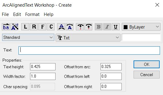
  Hello, Friends  Today We learn about ARCTEXT Command. Command : Arctext Menu : Express > Text > Arc-Aligned Text - We can write Text along an Arc using Arctext Command in AutoCAD Software. When We Select any Arc after applying Arctext Command. Following Arc options window is appear. Reverse Text Reading Order : Order of the Selected Arc- Aligned Text is Reversed. Alignment : Change the Alignment of Selected Arc : Left , Right, Center , Fit Position : Controls the Position of Arc- Aligned Text either Convex Side or Concave Side. Direction : Specify Direction of Arc-Aligned Text either outward from center or Inward to the center. Typeface : We can Apply Bold, Italic and Underline to selected Arc-Aligned Text. Color : We can change Color of Selected Arc-Aligned Text. Style : We can apply Text Style to Arc-Aligned Text. Font : Directly change the font of selected Arc-Aligned Text. Properties       Text Height : Change the Height of Arc-Aligned Text.      Width Factor : Chang

How to Edit Multilines using Mledit Command in AutoCAD Software?

Image
  Hello, Friends Today We learn about "Mledit" Command to edit Multilines. Command : Mledit Menu : Modify > Object > Multiline -We can edit Multilines at Intersection, We can break Multiline and We can edit Vertices of Multiline. 1) Closed Cross     Create a Closed Cross-Section Intersection between Two Multilines.     Select First Mline : Select the Foreground line.     Select Second Mline : Select the intersecting multiline. 2) Open Cross     Create an Open Cross-Section Intersection between Two Multilines.        Select First Mline : Select the Foreground line.      Select Second Mline : Select the intersecting multiline. 3) Merged Cross     Create a merged Cross-Section Intersection between Two Multilines.     Select First Mline then Select Second Mline. 4) Closed Tee     Creates a Closed- tee intersection between Two Multilines. The first Multiline is trimmed or extend            to its intersection with the second multiline. 5) Open Tee      Creates a Open- tee in

How to Create & Modify Multiline Style in AutoCAD Software?

Image
  Hello, Friends Today We learn about How to Create & Modify Multiline Style in AutoCAD Software. Command : Mlstyle Menu : Format > Multiline Style - Create & Modify Multiline Style. Set Current : Make Selected Multiline Style as Current Multiline Style. New : Create a New Multiline Style. Modify : Modify Selected Multiline Style. Can't Modify Current Multiline Style. Rename : Change the name of Selected Multiline Style. Delete : Deleted Selected Multiline Style. Can't Delete used and current Multiline Style. Load : Load Saved Multiline Style(.mln) into New Drawing file. Save : Save Multiline Style in .mln file format. Caps    a) Line             Start : Draw a line cap at Starting of Multiline.               End  : Draw a line cap at Ending of Multiline.     b) Outer Arc             Start : Draw Outer arc at Starting of Multiline.             End : Draw Outer arc at Ending of Multiline.     c) Inner Arcs             Start : Draw one or more Inner Arc between

How to Draw a Multiline in AutoCAD Software?

Image
  Hello, Friends Today We learn about Multiline Command in AutoCAD Software. COMMAND: MULTILINE SHORT-CUT: ML MENU : DRAW > MULTILINE - Multiline is a combination of Two or more Parallel Lines.We can explode Multiline and convert it into seprate lines. We can close Multiline using the Close Option. If We draw Multiline using Standard Style then only Two Parallel Lines are created. Scale(s) : Scale is considered as per Current Units in the Drawing. By Default, the Scale Value is 1.0 We can increase or Decease Value as per Drawing Requirements. If We take Scale Value Zero then only Single line is Created. Justification(j) : Specify the Justification for Multiline Top,Zero,Bottom. Justification determnines by from which side multiline is drawn. STyle(st) : Specify the Multiline Style for Multiline.By Multiline Style, We Can Create New Line & Modify Line.Rename & Delete Line from Multilines. Offset Distance of line from Middle line. Color & Linetype properties of each line.

How to Draw a Spline Curve in AutoCAD Software?

Image
Hello, Friends Today We will learn Spline Command in AutoCAD Software.  Command : Spline Short-cut : Spl Menu : Draw > Spline - Draw a Nonuniform Rational B-Spline(NURBS) curve passing through or near a set of fit points / Vertices. There are two options to draw a Spline : a) Fit b) Control Vertices(CV) We can draw a spline using many Fit points or many Vertices. Close(c) : Close Spline curve by joining Last point to Starting point. Method : Control whether the Spline Curve is created by Fit points or with Control Vertices.       Fit(f) :   Creates a degree 3 (cubic) B-spline by specifying fit points that the spline must pass through.              Knots(k) : Specify options when we choose Fit Method.             a)  Chord. ( Chord-Length method) Spaces the knots connecting each component curve to be proportional to the distances between each associated pair of fit points. An example is the green curve in the illustration.             b)  Square root. (Centripetal method) Spac

Draw Xline or Construction line in AutoCAD Software

Image
  Hello, Friends Today We will learn about Construction line / Xline in AutoCAD Software. Command : Xline Short-cut : Xl Menu : Draw > Construction Line - Construction line is a line with both sides infinite length. We can used construction line as reference line in drawing.Constuction line also known as Xline. We can trim Construction line. We can't give any dimension like Linear, Aligned dimension. Hor : Creates a Horizontal Xline passes through a point. Ver : Creates a Vertical Xline passes through a point. Ang : Creates a Xline at specific Angle or Reference which passes through a point. Bisect : Creates a Xline passes through angle vertex point and Bisect the Angle between Start point and End point. Offset : Creates a Xline Parallel to line, Xline or object. We can specify offset distance or we can create Xline Parallel to object by passing through a point.  Xline Command YouTube Video Link:     I hope You Like this Post. Subscribe this blog so you can get regular updat

How to use Ray in AutoCAD Software?

Image
  Hello, Friends Today We will learn Ray Command in AutoCAD Software. Command : Ray Menu : Draw > Ray - We can Draw Ray using Starting Point & Through Point. After Specifying Start point, We can draw multiple rays by clicking different through points. So Basically Ray is one sided infinite lines which have starting point but doesn't have ending point.   We can use Ray as Reference lines in AutoCAD Drawing. We can also use Ray for Projection of objects in Drawing. Ray Command YouTube Video Link: I hope You Like this Post. Subscribe this blog so you can get regular updates about this blog! If you have any doubt you can comment, we will reply to you as soon as possible. you can share this post with your friends, relative & Colleagues. In the next post, we will learn New AutoCAD Command / Topic. - Bhargav Joshi