Posts

Showing posts with the label AutoCAD 2D Draw Commands

How to write Singleine Line text or Dynamic Text in AutoCAD Software?

Image
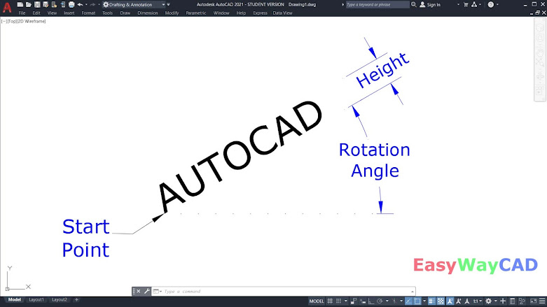
  Hello, Friends Today We learn about how to write text in AutoCAD Software? There are two types of Text in AutoCAD Software. 1) Singleline Text or Dynamic Text 2) Multiline Text Singleline text is used to write a Title, Heading or any single line text. Multiline text is used to write a paragraph text. First we see Singleline line text or Dynamic Text. Command : Text or Dtext Short-cut : DT Menu : Draw > Text > Singleline Text Click anywhere on Screen to Start the Text, You can specify Height and Rotation Angle.( Default Text Height=0.20, Text Rotation Angle=0) Justify       Left (L) : Specify Left alignment point for Text.Text Characters go from Left to Right in this option.     Right(R) : Specify Right endpoint for Text.Text Characters go from Right to Left Direction in this option.     Center(C) : Specify Center alignment point for Text.Text Characters go both in Left and Right side from Centerpoint.     Middle(M) : Specify Middle alignment point for Text. Text Characters

Working in Grid & Snap in AutoCAD Software

Image
  Hello, Friends Today We will learn about Grid & Snap in AutoCAD Software. Grid: The grid is a rectangular pattern of Dots or Lines. It Covers the entire XY Plane. It is very useful while aligning objects and visualizing distance between objects. Snap: Restricts the movement of the crosshairs to the intervals we define. While Working in Grid, Both Grid & Snap Mode should be ON. Use Ctrl+ G or F7 key or Mouseclick on Grid Icon on the Status bar to On/Off-Grid mode. Use Ctrl+B or F9 key or Mouseclick on Snap Icon on the Status bar to On/Off Snap mode. By default, the Grid Style is Lines. But we Can change the Grid style from Drafting Setting. Type DS Command > Snap and Grid > Grid Style > 2D Model Space. We can select 2D Model space, it converts into dots. Display grid beyond limits : If this option is selected, Grid is shown in the entire XY plane at UCS. But if we unchecked this option, Grid lines/dots are shown in specific limits set by Limits Command. By Default

How to create polyline or region object from Boundary Command in AutoCAD Software?

Image
  Hello, Friends Today We will learn about Boundary Command in AutoCAD Software. Command: Boundary Short-cut: Bo Menu: Draw > Boundary - By Boundary Command, We can create Region or Polyline Object from Closed Bounded ( Enclosed) Objects. Pick Points: By this Option, A boundary is determined from existing objects that form an enclosed area around a specific point. Island Detection: By this option, We can controls whether internal boundaries ( Island) are detected or not. If We Check this option, then All internal boundaries create regions or polylines objects. Object Type: Controls New Boundary create a Region object or Polyline object. Boundary Set: Selected objects are form a Boundary set while analysing boundary.         Current Viewport: Create a New Boundary set in Current Viewport.         New : We can selecte objects which define new Boundary Set.Boundary includes only thosed objects which create a region or polyline object when construct a new boundary set. Boundary Comm

How to convert selected objects into Region object in AutoCAD Software?

Image
Hello, Friends Today We will learn about Region Command in AutoCAD Software. COMMAND: REGION SHORT-CUT: REG MENU: DRAW > REGION Convert Selected Closed bounded (Enclosed Area) objects into Region Object. We can select Lines, Arcs, Polylines, Ellipses, Elliptical Arcs & Splines to Create Region Object. Crossing & Self intersect objects are not valid to create a Region Object. We can use Union, Subtract & Intersect Commands on Region objects. We can't Stretch Region Objects. We can also use Boundary Command to create a Region Object. Region Command YouTube video :  https://youtu.be/M9rZSzMvkQ0 I hope You Like this Post. Subscribe this blog so you can get regular updates about this blog! If you have any doubt you can comment, we will reply to you as soon as possible.you can share this post with your friends, relative & Colleagues. In the next post, we will continue to about AutoCAD Commands. - Bhargav Joshi

How to draw an isocircle in AutoCAD Software without using Isometric snap?

Image
  Hello, Friends Today We will see how to draw an Isocircle without using Isometric Snap. First Draw Cube by lines in 2D Using Polar Tracking: ON. Take Increment Angle value 30 so we can draw lines on 30,90 & 150 angles. Use F10 key or Ctrl+U to ON Polar Tracking or Click on the Status bar. Now Draw Circle and use trim to draw an isocircle. See below Fig. To see in detail. See youtube Video. Isocircle Youtube Video Link:  https://youtu.be/YSavWn6tIFE I hope You Like this Post. Subscribe this blog so you can get regular updates about this blog! If you have any doubt you can comment, we will reply to you as soon as possible.you can share this post with your friends, relative & Colleagues. In the next post, we will continue to about AutoCAD Commands. - Bhargav Joshi Follow, Subscribe, Share &  Like Page: Email us: easywaycad@gmail.com  for any query.