How to Give Dimensions in AutoCAD - Part 3
Hello, Friends
Today We will Learn How to Apply Dimspace, Dimbreak, Diminspect, Dimjogline & Oblique Dimensions in AutoCAD Software.
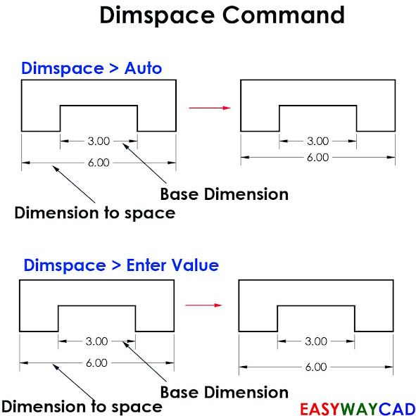
Command: Dimspace
Menu : Dimension > Dimension Space
- Adjusts the Spacing between linear or Angular Dimensions.
Select Base Dimension: Select the Linear or Angular Dimension from which the others will be spaced.
Select Dimensions to Space: Specify Parallel Linear or Angular Dimensions to space Equally from Base Dimensions. We can select one or more Dimensions to space from Base Dimension.
Enter Value: Type Value for spacing between Selected Dimensions.
Auto: Calculates the spacing distance automatically based on the text height. Auto Space is double the height of Text. i.e. If Text Height is 0.18 then Auto Spacing is 0.36
Command: Dimbreak
Menu : Dimension > Dimension Break
- Breaks and Restore Dimension and Extension Lines where they cross each other objects.
Multiple: Add Break or Remove Break from Multiple Dimensions.
Auto: Place Dimension Breaks Automatically at all Intersection Points of the Objects that intersect the selected Dimension.
Remove: Remove all Dimension Breaks from Selected Dimensions.
Manual: Place Dimension Break Manually. Specify Two Break Points on Dimension line, Extension line or Multileader line.
Command: Dimjogline
Menu : Dimension > Linear Jogged
- Add or Remove Linear Jogged lines on a linear Dimension. We can only apply one linear jogged at a time on a linear dimension. We can reposition linear Jogged lines on a Linear Dimension.
Select the Linear Dimension and place a point to located Linear Jogged.
Remove: Remove Linear Jogged lines from Selected Linear Dimension.
Command: Dimedit
Menu : Dimension > Oblique
The Oblique option is useful when extension lines conflict with other features of the Drawing. the Oblique Angle is Measured from the X-axis of the UCS. We can use the oblique dimension in Isometric Drawing to align with Isoplane.
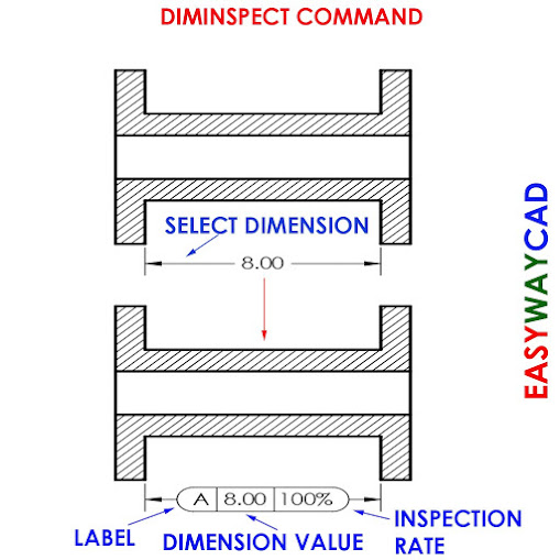
Command: Diminspect
Menu : Dimension > Inspection
- Add or Remove Inspection Information to Selected Dimension.
1) Round: Create a frame with semi-circles on both ends. Fields within the frames are separated by Verticale lines.
2) Angular: Create a frame with lines that form a 90-degree angle on the two ends; Field within the frames are separated by Verticale lines.
3) None: No frame is drawn around the values. Fields are not separated by the Vertical liens.
Label: Specify the text that appears on the Label.
Inspection Rate: Specifies what percentage of time a dimensioned part should be inspected.
Jogged Linear, Inspection Dimension, Oblique Dimension
Video Link :
I hope You Like this Post. Subscribe to this blog so you can get regular updates about this blog! If you have any doubt you can comment, we will reply to you as soon as possible. you can share this post with your friends, relative & Colleagues.


Comments
Post a Comment
More Information Contact US on email.